


8.1. ARS study in Crimea at the place Patil.
 In
this section some field results, collected in Crimea at Geological faculty
of MSU' training base are submitted.
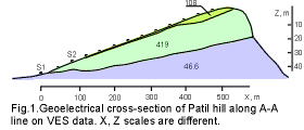
The study was carried out at place Patil. Patil is a hill, where softer
anisotropic rocks of the basement (dipping nearly vertically) are partially
covered with harder horizontal layer of sandstone, with the thickness up
to 25 m (fig.1).
This place is traditionally and for a long time used for student practice
to show effects of rock anisotropy.
 In
place of anisotropic rock outcrop (S1) ARS with any array gives appreciably
extended diagrams. In the last years our studies were concentrated on territory,
where the anisotropic basement was covered with the sandstone layer. All
attempts to receive here effect of anisotropy with Schlumberger array were
unsuccessful. Only non-linear array (like dipole equatorial) has enabled
to estimate confidently properties of the anisotropic basement. To understand
the reason of these effects, in two sites (S1 and S2), where the anisotropic
basement outcrops and is covered with a thin sandstone layer, we made azimuthal
soundings with AMN (E) and dipole equatorial (D) array. AR soundings were
measured on 12 azimuths with a step 30° and with spacing from 1.5 up
to 50 m and from 5 up to 75 m in S1 and S2 accordingly. At each sounding
MN line remained fixed in the center, and electrode A or dipole AB was
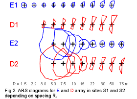
moved around. The azimuthal diagrams for various spacings for two arrays
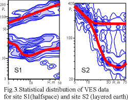
are shown on fig.2. VES statistical processing has allowed to draw sounding
results as probability distribution in coordinates apparent resistivity
- distance, the examples of which for D-array are shown on fig.3. In both
cases the distributions are bimodal and marked by two modal curves drown
also on fig.3. The upper curve in site 1 corresponds to longitudinal array
orientation and looks like two-layered one with resistivity ratio greater
then 1. The lower curve corresponds to transversal array orientation and
looks like three-layered H-type curve. Difference between these curves
is about ten times in resistivity level. The curves for S1 show that the
medium in this place is not uniform half-space and the reason of that is
probably in effect of weathering. VES curves for the site 2 with overburden
are also different for longitudinal and transversal directions. Longitudinal
curve looks as descending two-layered one, whereas transversal curve looks
as three-layered H-type curve. Theoretical accounts have confirmed, that
the difference between both curves and the layer H on the last curve arises
from the anisotropy influence. The further data processing was made with
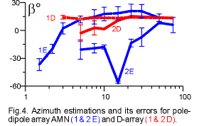
the help of spectral approach. Spectral approach allows to define a strike
azimuth and an error of that estimation. On fig.4 azimuths' estimations
for different spacings and their errors for E and D array are submitted.
The error for E array is much more that for D-array. The error for D array
is small and frequently is not seen clearly on fig.4.
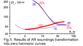
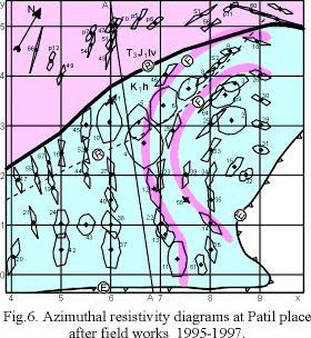 Fig.5
gives an example of spectral transformation of AR soundings into sounding
curves without influence of anisotropy. That can be done with 0-harmonics
of AR soundings. As we saw on fig.2, ARS diagrams for E and D arrays were
different, but 0-harmonics for both arrays on fig.5 are very similar, and
can be interpreted as usual VES curves.
On fig. 6 azimuthal diagrams for nearly one hundred ARS sites on Patil
are presented. To the South from line B the anisotropic basement is covered
with the layer of sandstone. The north part of the area is situated on
the outcrop of the basement. Some diagrams at the North were measured with
D-array spacing from 20 to 40 m. All other ARS were measured with array
spacing from 40 to 120 m. The rotation of D-array was executed around the
spacing center. The choice of D-array electrode spacing depending on proposed
thickness of sandstone cover, was justified with the help of theoretical
modeling (Bolshakov et al. 1995). The difference in the shape of the AR
diagrams S2, 8, 7, 6, 5, 10, 4 results from the gradual increase in the
thickness of the upper layer. The difference in the shape of AR diagrams
2 and 25 is a result of a change in array spacing (40 and 120 m). Delineation
of the strike in the basement rocks with AR diagrams helped to map a fold,
situated in the right part of fig.6. The form of the fold is marked by
lines with the letter F. The abrupt edge of Patil hill in the South and
the East is marked by a line with letter E. Line A-A is VES profile (see
its results on fig.1).
119899, Russia, Moscow, Moscow State University, Geological
Faculty, Department of Geophysics
V.A. Shevnin, I.N. Modin
Tel. & fax: (7-095) 939 49 63
E-mail: sh@geophys.geol.msu.ru
Please feel free to send us
your comments.


 In
place of anisotropic rock outcrop (S1) ARS with any array gives appreciably
extended diagrams. In the last years our studies were concentrated on territory,
where the anisotropic basement was covered with the sandstone layer. All
attempts to receive here effect of anisotropy with Schlumberger array were
unsuccessful. Only non-linear array (like dipole equatorial) has enabled
to estimate confidently properties of the anisotropic basement. To understand
the reason of these effects, in two sites (S1 and S2), where the anisotropic
basement outcrops and is covered with a thin sandstone layer, we made azimuthal
soundings with AMN (E) and dipole equatorial (D) array. AR soundings were
measured on 12 azimuths with a step 30° and with spacing from 1.5 up
to 50 m and from 5 up to 75 m in S1 and S2 accordingly. At each sounding
MN line remained fixed in the center, and electrode A or dipole AB was
moved around. The azimuthal diagrams for various spacings for two arrays
are shown on fig.2. VES statistical processing has allowed to draw sounding
results as probability distribution in coordinates apparent resistivity
- distance, the examples of which for D-array are shown on fig.3. In both
cases the distributions are bimodal and marked by two modal curves drown
also on fig.3. The upper curve in site 1 corresponds to longitudinal array
orientation and looks like two-layered one with resistivity ratio greater
then 1. The lower curve corresponds to transversal array orientation and
looks like three-layered H-type curve. Difference between these curves
is about ten times in resistivity level. The curves for S1 show that the
medium in this place is not uniform half-space and the reason of that is
probably in effect of weathering. VES curves for the site 2 with overburden
are also different for longitudinal and transversal directions. Longitudinal
curve looks as descending two-layered one, whereas transversal curve looks
as three-layered H-type curve. Theoretical accounts have confirmed, that
the difference between both curves and the layer H on the last curve arises
from the anisotropy influence. The further data processing was made with
the help of spectral approach. Spectral approach allows to define a strike
azimuth and an error of that estimation. On fig.4 azimuths' estimations
for different spacings and their errors for E and D array are submitted.
The error for E array is much more that for D-array. The error for D array
is small and frequently is not seen clearly on fig.4.

 In
this section some field results, collected in Crimea at Geological faculty
of MSU' training base are submitted.

 Fig.5
gives an example of spectral transformation of AR soundings into sounding
curves without influence of anisotropy. That can be done with 0-harmonics
of AR soundings. As we saw on fig.2, ARS diagrams for E and D arrays were
different, but 0-harmonics for both arrays on fig.5 are very similar, and
can be interpreted as usual VES curves.